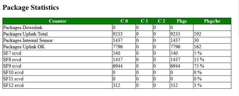
When the gateway is configured well, this is (part of) the screen that you will see on the browser. This chapter will show you how to configure the software of the gateway in order to transfer incoming LoRa messages.
This is the 6th generation of software implementing LoRa gateway function on a platform consisting of an ESP8266 mcu and a SX1276 radio. Unlike the previous versions of the gateway, it will listen to all available Spreading Factors on a single frequency.
The software does in principle support up to 3 multiple channels, but the HOP software to support this is not (yet) reliable. Also, the function to support downstream messages does not yet work for 100%.
The single channel gateway can be used for multiple purposes:
This documentation describes the installation, configuration and use of the software. Please disable all functions you do not need for the first usage of the gateway and enable new functions step by step. There are MANY parameters to set and therefore it is easy to fail setup.
The documentation of the Single Channel Gateway is found in the following documents:
Maybe we'll add a technical manual to explain why certain solutions or settings were chosen for the Single Channel Gateway.
LoRa stands for Long Range and is a next generation Internet of Things communication protocol to have "Things" communication with a backend over a long range and with low power too. This comes at a price however, the LoRa transceiver devices will only work over a long range if the devices (things) will transmit and receive short and simple messages and the frequency of this communication is kept low.
Although there are more components involved in the LoRa network, for simplicity we can divide the components into three major categories:
LoRa sensors are mostly transmitters of simple messages. Several sensors are described on the documentation pages. Well known examples are temperature sensors, air pressure, humidity, distance, movement (PIR) etc. In itself single sensors might not be very interesting, however when there are lots of them for example reporting the humidity of soil every acre of farm grounds, it enables effective water management for farmers.
The backend receives the sensor messages and distributes them based on their idents and security parameters to one or several applications. These application turn the data of the sensors into information for the applications and as such they are maybe the most important component in the process. Applications might gather data and turn it into user information o GUI's, store in databases for later analysis etc.
Gateways receive sensor data over the air, do some decoding and transport the data to the internet backend. As such they are a vital element in the chain but as they have no knowledge of the data content of the sensor messages their use is limited to transport only. Gateways can also send messages to sensors for example provide them with addresses in the network, activating sensors (similar to WiFi addresses being managed by Routers).
There are three modes of operation for gateways:
The gateway described is not a full/standard LoRa Gateway. A compliant LoRa Gateway should support all Spreading Factors (SF7-SF12) and should support at least three frequencies. Our Single Channel Gateway does not do this. Instead it only sends and receives on one frequency (channel) like the name does suggest.
The user should therefore be well aware that unless the sensors will use the same one channel too, that the gateway will receive on average only one out of 8 messages. So it could be that the gateway does not receive ANY of the messages of a certain node although both the sensor and the single channel gateway are working perfectly.
The single channel gateway knows 3 modes of operation:
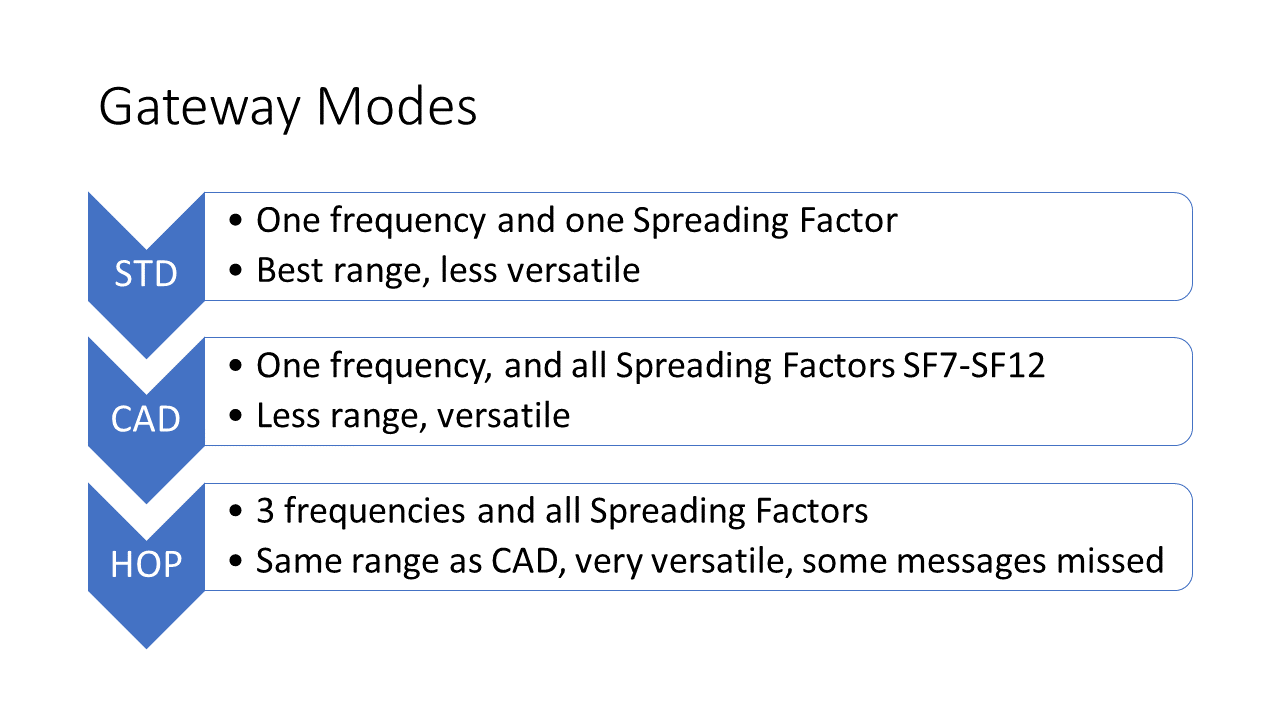
In single channel gateway standard mode, the user can select the frequency and the spreading factor to use for reception of messages. the Gateway will behave like a real single channel gateway; just one frequency and one spreading factor can be set.
the advantage of the STD mode is, that as we know on what frequency and spreading factor we listen for new messages to arrive, the whole configuration is tuned towards this use. For example: We can receive message with a very low RSSI (-120dB or lower), something that is not possible with CAD mode of operation. Also, this mode may be a little more reliable although we have no indication that the system will miss more messages when in CAD mode.
The frequency and the spreading factor can be set as a default in the ESP-gway.h file or can be set (and changed) using the webserver interface.
Channel Activity Detection (CAD) is a function of the LoRa radio. It means that the radio detects whether another LoRa device in range is transmitting and when the receiver senses that, the device will not transmit on that channel or spreading factor to avoid a collision. During a short time before the actual transmission of data (payload) begins, each transmitter send out preamble signals indicating to other devices that a device is ready to transmit data.
Although CAD is designed to be used by nodes to detect other activity on a given frequency/spreading factor combination, it can be used by our single channel gateway as well. If the gateway can use CAD functionality to detect incoming messages on a given band, we can quickly set the receiver to that frequency and spreading factor and receive the incoming message.
Now we have CAD mode with all its advantages, why would we ever use STD mode? The answer lies in the way we use the CAD functions in our gateway code. In our code we put the chip in CAD mode and set the interrupt so that we receive an CADDONE interrupt once the radio detects activity from other nodes. This tells us that someone is starting transmission on our current frequency.
The radio will get this interrupt for its current frequency but it does not know on which spreading factor the remote node is going to send a message.
So next we check on the rssi (signal strength), we use the normal rssi of the sx1276 and subtract 157 for correction. The resulting number is the rssi of the receiver. (The package rssi (prssi) is another parameter that describes the rssi of the last package received, but it is not used in CAD mode). When we receive a CADDONE interrupt with a high rssi, we probably will receive a message on that frequency soon. So we need to figure out at which spreading factor the sender is starting its transmission. Therefore we will start with SF7 and move up to the next factor until we receive a CADDETECT interrupt on DIO1. The RSSI parameter that determines whether there could be a message arriving on the radio receiver can be configured in the loraModem.h file by setting the RSSI_LIMIT definition. The default value is 40, but it can be set to other values as well.
Once we receive the CADDETECT interrupt on DIO 1 we know that there is a message coming on our current frequency and spreading factor. We then put the radio in message receive mode and wait for the RXDONE interrupt that tells us that the complete message has been received and is ready in the FIFO buffer.
Should for whatever reason no message arrive within a certain time, we will receive the RXTOUT (timeout) interrupt instead telling us that there was a timeout and no message has been received.
If we have receive a message, we set the state variable so that in the next loop() iteration the message is read from the FIFO buffer.
Next, whether we receive a message or not, the mode is set to scanning again.
RSSI stands for Received Signal Strength Indicator is is measured on the receiver to determine the signal quality of the sender. Normal RSSI can be measured any time at the receiver side by reading register 0x1B. The SX1276/RFM95 transceiver contains a special register 0x1A that contains the average packet RSSI information.
The RSSI function is used by CAD to determine if we have received a message. This is not as the RFM95 is designed, after all new messages might be received that are below the noise floor and this using RSSI is not the most reliable process.
The correct RSSI sample can be computed (according to the RFM95 manual para 4.2.5.3) by adding TS_RE + TS_RSSI
Using CAD mode has several advantages over STD more. Selecting CAD makes the gateway a lot more versatile and it will receive message from SF7 to SF12. And although the reception will probably not be quite as sensitive as a "real" gateway for most applications it will do the job.
This mode is very experimental, and does not work yet the way it is intended.
Using HOP mode, the system will have same functions as CAD mode but have the additional value of listening to messages on 3 frequencies as well.
The frequency hopping function is more difficult to implement than the CAD function. This is because CAD does work more or less automatically for a given frequency and the receiver can wait for the CADDONE interrupt telling that there might be a message waiting on one of the spreading factors for that frequency.
For frequency hopping this does not work as there is no mechanism that tells us that there might be a message arriving on another frequency than the one we're tuned in an the moment. So, if we want to implement a reliable frequency hopping function we must set a timer interrupt that fires once there is no incoming activity detected within a certain time on the frequency.
So what is the ideal waiting period for the hopping mode, and how do we implement a timer.
re 1. The timer period should be long enough to determine that there is no activity on that frequency. So we should only switch when state is S_SCAN.
re 2. It is possible to connect an external clock/timer and connect it's pin(s) to one of the free GPIO pin's of the ESP8266, or it's possible to use one of the internal timers for this purpose. The first one is an option but will make the code a lot more complex and add extra hardware to the gateway. The second option internal timer is an option but only if its use does not interfere with the internal administration functions of the ESP8266 (such as Wifi handling etc.).
So taking both options into account it may be an option to just use the microsecond timer for his purpose yet do not use any interrupt processing, but instead use the loop() function itself. Timeout is about 2500 uSec before switching.
If the HOP mode works without problems, it makes our gateway more or less a "real" gateway that supports 3 frequencies and all Spreading Factors.
(*** DRAFT ONLY ***)
As mentioned before, mode B (beacon) operation is not yet supported. The LoRa Specification 1.1 details the beaconing process used for Class B support. Chapter 9 deals with the principles of Class B support. Please note that gateway support for Class B is optional. All Gateways joining in the support of Class B should synchronize their beacons (although the individual nodes should be able to deal with all beacon messages). Nodes should select the closest and strongest gateway available.
The 1.1 spec is divided in two sections: (1) One for the network/gateway and (2) a section for the end-nodes. We stick to the gateway in this document.
We deal with individual end-nodes only (NO multicasts for the moment). It means that the end-node should communicate to the gateway the following information. The 1.1 specification mentions this is out-of-band communication (not standardized).:
When the gateway communicates a beacon to the end-nodes in contains information abount the timing. It will transmit information to the end-nodes during these "pings" and the devices should open a receive windows during this time to receive the information of the gateway/network,
This will enable the end-nodes to receive infoamtion from the network even when it does not send information to the gateway itself. RTemember that receiving information is far less power-consuming that sending it to the network. So although receiving every two minutes will cost more power than receiving only after sending to the gateway (which may take hours) it will enable the end node to react on things (like expolicetly changing spreading factor for example).
The gateway chosen by the network should communicate with the end-node on the opened ping slot. However, all gateway should be informed about thit communication and all should send out beacon. This will enable end-nodes to move around. It is not yet clear what the network will do als whether all networks will accept the Class B operation.
As tousands of devices can connect to the gateway I do not assume that gateways will send out beacons for every connect end-device. So instead a multicast will probably be used with well-known parameters for frequency and speed and of course the ping-slot.
(*** NOT SUPPORTED ***)
As mentioned before, mode C (continuous) operation is not yet supported. Class C (or Mode C) devices are used when extremely low power is not an issue for a node. Semtech has written the following paper to illustrate the working of a Class C device.
Datasheets for RFM95 and SX1276 should be the same. However, the HopeRF document contains confusing information especially in the registers description are where RSSI for example (register 0x1B ?) is concerned.