This page describes how to modify the hardware and software of the Mini LoRa Node so that we can connect I2C bus sensor(s). The HTU21 is such a sensor and it measures temperature and humidity and therefore is our ideal candidate.
Apart from adding this hardware to the node, we also need to make some modifications to the sketch code in order to support the I2C bus and the LowPower functions..
How to make the node itself is described on the first page. Please read the page <HERE>
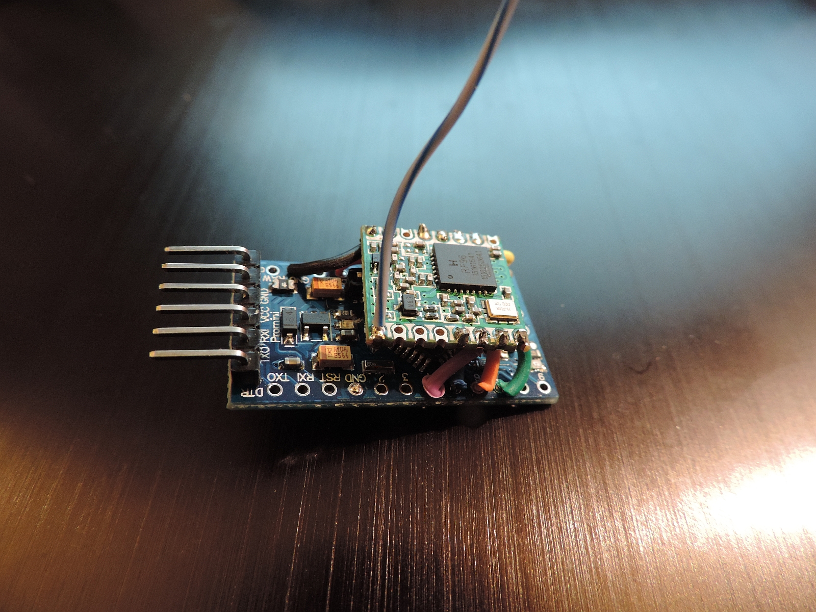
So the following connections need be made, please click on the picture to enlarge the image.
The sketch for running the Mini Node and Sensor can be found on Github. This sketch uses a tiny stack where several functions are not implemented, the most important being that this stack does not use multiple channels. This stack has a real low-power variant implemented, which makes it run on batteries for a long time.
So there is an alternative stack available based on the IBM LMIC software, I called it the LMIC-1.51 version. It can be found on Github. The negative of using this stack is that there is less program and memory space available for sensor code since the stack itself is a big-spender. The positive: It uses the reference implementation.
ToDo: I need to merge the LMIC-1.51 library with low-power so that a sensor will run for a longer time on the software (probably by disabling receive functions and sleep in between transmissions).
The I2C bus is standard on Arduino devices. Devices on the bus are connected by 4 wires: Vcc, Gnd, SDA and SCL. The SDA pin is connected to pin A4 on the Arduino and SCL on pin A5 (Please note A4 is the Analog pin 4!).
In principle, multiple devices can be connected to the bus, which means we can daisy chain the devices and we do not need more pin's but all are connected to SDA/A4 and SCL/A5
The RFM95 uses 1.8mA in normal mode of operation. The machine is then always ready to transmit and receive messages. As we like to operate our node on batteries, best is to NOT receive any messages and only report/transmit sensor values every once in a while. Therefore there are two things we need to do:
Measuring the remaining battery power is is a very useful thing for battery operated sensors. So if the battery level drops below a certain value (say 1.1 Volts for a AA Alkaline cell) we see an LED blinking on the sensor board or we receive special battery sensor messages from the sensor (or both).
The Arduino has an internal Analogue-Digital Converter (ADC) on board that can measure a voltage level and return a digital value indicating the level measured. The Arduino ADC has an internal reference value of around 1.1Volts DC, which means that when we measure 1.1V we receive the maximum measured value (and when we measure a voltage level of 0 Vdc this is 0). So for our 2 AA-cell battery which has a voltage of 2 * 1.6 = 3.2 Vdc. Therefore, the max is 3.2Vdc for fresh batteries and below (2 * 1.2 = ) 2.4 Vdc we should rapidly replace the batteries.
The solution is to build a voltage divider with two resistors so that the resulting Voltage at the measuring analog pin will not exceed this 1.1V internal reference value. When we take into account that the input voltage of the battery will be 3.2 Vdc of evel a little higher, the voltage devider resistors will be of value 1.0 M and 330K Ohms.
As said the value we get in return is and integer value between 0 and 1023. So we might convert this back to Voltage by multiplying with 4.45 (This is the input voltage for which the voltage devider more or less provides the reference votage of 1.1 V dc) and then dividing by 1023.
There is always room for improvement: